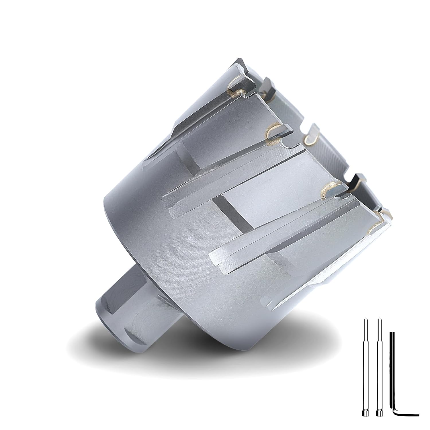
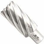
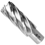
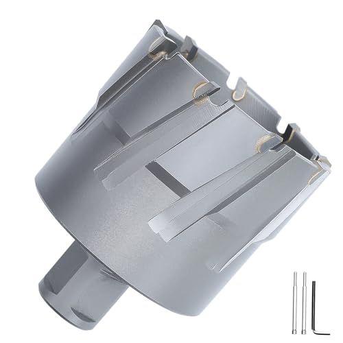
The GRIXLEN 3-3/4″ Weldon Annular Drill Bit is a robust tool. It is like a tiny, but powerful, cookie cutter for metal. This drill bit creates clean holes. It is 3-3/4 inches in diameter. Also, its cutting depth is 1-3/8 inches. The drill bit has carbide tips. These tips are super hard. They make drilling stainless steel easy. Iron is also no match. Furthermore, it features a Weldon shank. This shank ensures a secure fit. Thus, it prevents slippage during use. This GRIXLEN 3-3/4″ Weldon Annular Drill Bit is truly impressive. It handles tough metals well.
Moreover, this annular cutter is efficient. It removes material around the hole’s edge. This is different from a regular twist drill. Twist drills cut the entire hole. However, this annular bit is faster. It requires less power. Therefore, it is ideal for heavy-duty tasks. The carbide tips stay sharp. This means longer tool life. Consequently, you save money. The design minimizes friction. This reduces heat build-up. Plus, it improves hole quality. The GRIXLEN 3-3/4″ Weldon Annular Drill Bit is a true workhorse. It is a reliable choice for metalworking.
Finally, consider this drill bit for your projects. It offers precision. It also provides durability. The carbide tips are very effective. They cut through challenging materials smoothly. Stainless steel and iron are no problem. The Weldon shank adds stability. This bit is user-friendly. It performs consistently. Therefore, it is a great investment. Indeed, it streamlines drilling operations. Ultimately, the GRIXLEN 3-3/4″ Weldon Annular Drill Bit delivers exceptional results. It makes drilling large holes simpler.
FEATURES:
– Brand: GRIXLEN
– Cutter diameter: 3-3/4 inches
– Shank type: Weldon
– Tip material: Carbide
– Drill bit type: Annular
– Depth of cut: 1-3/8 inches
– Material suitability: Stainless Steel
– Material suitability: Iron
– Tool type: Annular Cutter
– Application: Drilling
This GRIXLEN annular cutter is a special drill bit. It has a carbide tip, which makes it very strong. The cutter is 3-3/4 inches wide and can drill a hole 1-3/8 inches deep. It has a Weldon shank that helps it fit into certain drills. This tool works well for drilling holes in tough metals like stainless steel and iron.
– Cuts extremely well
– Good job of chip evacuation
– Cutting action is very smooth
– Cutting teeth are durable
– Long lasting
– Impressive – Solid Construction
– Very Durable and Reliable
– Decreased our Production Times
– Produces Professional Results
– Fits Vevor magnetic drill
– Cut through 20 holes in 1/4
– Eats steel like it should
– Performs great on stainless steel and iron
– Cut smoothly and efficiently
– Producing clean, accurate holes
– Maintained its sharpness
– Fits securely in my mag drill
– Cuts easily through Stainless Steel
– Cutter does not cut stated size
– Cutter is way oversized
– Failed after only 16 holes
– Carbide bits stripped off
– Less good chip evacuation over 1/3 inch
The GRIXLEN 3-3/4″ x 1-3/8″ Annular Cutter with Weldon Shank is a highly effective tool for drilling through tough metals like stainless steel and iron. Users consistently report that it cuts exceptionally well, producing smooth, clean, and accurate holes while significantly reducing production times. Its carbide-tipped teeth are durable and long-lasting, maintaining sharpness even after numerous uses, and its solid construction contributes to its impressive durability and reliability. The cutter also excels at chip evacuation, though some users noted it was less effective on thicker materials. It fits securely in magnetic drills, including Vevor models. However, some users have experienced issues with the cutter not cutting to its stated size, being oversized, or failing prematurely after a limited number of holes, with carbide bits stripping off. Read more…