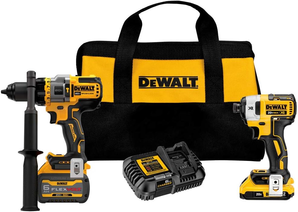
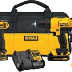
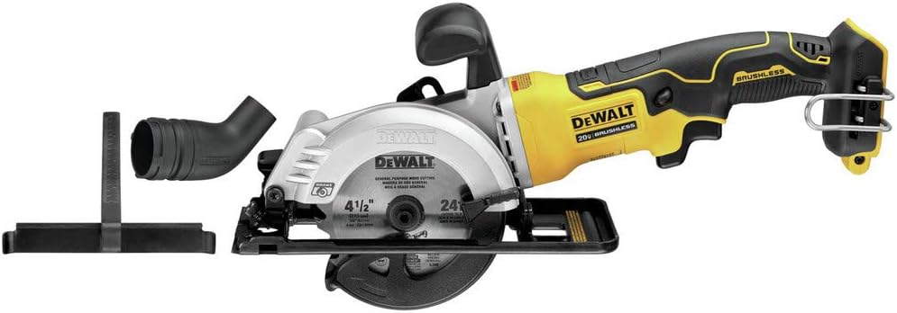
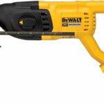
If you are looking for a reliable power tool kit, the DEWALT DCK2100D1T1 is a strong contender. This DEWALT 20 Volt FLEXVOLT ADVANTAGE Kit is like having a superhero in your toolbox. It combines a powerful hammer drill/driver and an impact driver. Both are brushless, meaning they run cooler and last longer. Furthermore, the hammer drill boasts FLEXVOLT ADVANTAGE technology. This means it gets more power when paired with a DEWALT FLEXVOLT battery. Thus, you get extra oomph for tough jobs. Consequently, drilling through concrete becomes much easier. Moreover, the kit includes a 2.0Ah 20 Volt MAX* battery and a 6.0Ah FLEXVOLT battery. It also comes with a charger and a bag. This is a complete package.
The hammer drill/driver is a true workhorse. It tackles many tasks. Think of it as a Swiss Army knife. It handles drilling into wood, metal, and even masonry. Plus, the impact driver is incredibly fast. It drives screws quickly. It’s like a cheetah, swift and powerful. Together, these tools form a dynamic duo. They make projects much more manageable. They reduce fatigue too. Therefore, your hands will thank you. This DEWALT 20 Volt FLEXVOLT ADVANTAGE Kit truly delivers. You will notice the difference.
Overall, this DEWALT 20 Volt FLEXVOLT ADVANTAGE Kit is an excellent investment. It is built to last. The tools feel solid in your hand. They are reliable companions for any DIY enthusiast. Even professional tradespeople will appreciate them. So, if you need dependable power tools, consider this kit. It offers great value. It performs exceptionally well. Ultimately, it makes your work easier. You won’t be disappointed.
FEATURES:
– Brushless motors
– 2-tool kit
– Hammer drill/driver included
– Cordless design
– 20 Volt MAX* power
– FLEXVOLT ADVANTAGE
– Compact size
– Lightweight build
– Variable speed trigger
– LED work light
The DEWALT DCK2100D1T1 is a 2-tool kit that runs on a 20 Volt MAX* battery. It includes a hammer drill/driver that uses a special FLEXVOLT ADVANTAGE system, which gives it more power. Both tools have brushless motors, making them efficient and long-lasting. They are cordless, so you can use them anywhere. The tools are small and light, making them easy to handle. They also have a variable speed trigger, letting you control the speed, and an LED light to brighten your work area.
– Arrived sooner than expected
– Works like a dream
– Does any and all jobs
– Excellent product
– Highly recommended
– Perfect fair deal
– Pura calidad
– Worth every penny
– Great seller and item
– Both units work good
– Really kick up a notch with FlexVolt
– Made light work of anchoring
– Drill is excellent
– Top end set
– Very powerful tools
– Hammer Drill is a beast
– Does concrete job perfectly
– Impact drill very comfortable
– Impact drill minimal
– Impact drill powerful
– Outstanding seller service
– Seller solution above expectations
– Package arrived in a beat up box
– 6ah 20Volts Battery…came flatline
– Have to go purchase 2 batteries
– Pricier than others
– Can find a better value with a lower set
This DEWALT DCK2100D1T1 20 Volt MAX* Brushless Cordless 2-Tool Kit, which includes a hammer drill/driver with FLEXVOLT ADVANTAGE, has been praised by users for its excellent performance and power. Many found the tools to work exceptionally well for all types of jobs, including drilling into concrete, and highlighted the comfortable and powerful nature of the impact drill. The kit arrived sooner than expected for some, and users felt it was a fair deal and worth the price, with the FlexVolt feature significantly improving performance. However, some customers received the package in a damaged box, and one reported a flatline 6ah 20 Volt battery, necessitating an additional battery purchase. A few also noted that the kit was pricier than other options and that better value might be found with a lower-end set. Read more…